"Cross Scale" implementation by the "Profile" ScenarioPoster Presentation for the "Cross Scale" meeting |
Abstract
|
The Idea
Here is an idea worth considering. . .
"Profile" is a proposed constellation of 12 small satellites to study the structure of the magnetosphere, on both global and small scales. The spacecraft form two groups (6+6) on a pair of adjacent eccentric orbits, with apogee of 20 or 25 RE, members of each group passing their near-Earth perigee about 1 hour apart.
The faster group overtakes the slower one 4-8 times a year, and when it does [Figure 2], instruments can be intercalibrated and a 2-point correlation functions can be derived, simultaneously at up to 6 locations. Because orbital motion near apogee is slow, satellites will cluster together there; this happens to each group every orbit, but a larger supercluster, useful for reconnection studies, is formed when the faster group is overtaking.
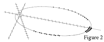
With a properly timed orbit of about 10° inclination, when apogee (and clustering) occurs at midnight, the tail's "warping" effect allows the plasma sheet to be observed, while eclipses are held to last no more than 2 hours.
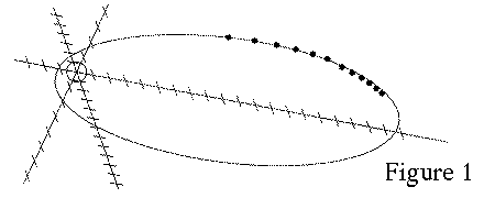
At other times, satellites are spread out linearly [Figure 1], able to follow the earthward progress of substorms (on the night side), shocks (on the day side), particle injections and other events. When the orbital axis is in the dawn-dusk direction, the thickness and variation of the low latitude boundary layer can be compared at two separated locations (testing for propagating waves, etc.). Throughout the mission the ring current can be monitored with traverses as close as half an hour (and even closer for paired observations).
The satellites would resemble ST-5, with mass around 20 kg and with magnetometers and ion/electron detectors that cover nearly 4π. Spinning at 20 RPM around an axis perpendicular to the ecliptic, they can also use a "driftmeter strategy" to obtain two near-equatorial components of the bulk flow.
The "Centrifugal Slingshot" and "Twin Profile"
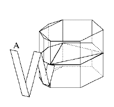
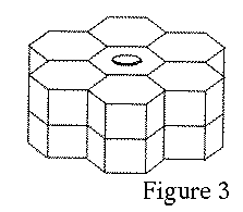 The above orbits are produced by a "centrifugal slingshot" strategy. Individual satellites are clustered in groups of 6 [schematic view in Figure 3] around the axis of a "mother ship, " which has propulsion and attitude control. The mother ship is first (1) placed in a circular parking orbit, then (2) a second burn at the proper moment raises apogee to 20 or 25 RE, and (3) a third small burn at apogee adjusts orbital inclination.
It then (4) despins, (5) turns by about 90° to align its axis perpendicular to the ecliptic, and (6) is spun up to 20 RPM, perhaps by small rockets. The satellites meanwhile slide out on short booms, to rotate about 1 meter away from the axis.
On each of the next 6 perigee passes, two oppositely placed satellites are released simultaneously, keeping the assembly balanced. Always, one satellite is flung forwards in the orbit, giving it a higher apogee, while the other is flung backwards to a lower apogee. The mother ship keeps orbiting, say with a period of 67 hours (for apogee 25 RE). The satellites continue to spin at 20 RPM on an axis perpendicular to the ecliptic, but in addition, the linear velocity imparted to them when released, though no more than a few meter/sec, is enough to give them orbital periods 1 hour shorter or longer than that of the mother ship.
Each perigee pass another pair of satellites is released, creating in the end two strings of 6 spacecraft each. The satellites need no additional propulsion, and the mother ship may also be instrumented.
A particularly attractive variation is the "Twin Profile" option, where two identical mother ships start from an identical parking orbit, but take off towards apogee (step #2 above) on ellipses 180° apart. Such a mission has 24 satellites, and coverage is doubled--twice a year in the plasma sheet, taking advantage of the warping both times [Figure 4].

But there exist extra benefits. Simultaneous linear coverage can now extend from the foreshock to the mid-tail, and (3 months later) from flank to flank, tracing any asymmetry in the y-direction. It turns out that gravitational perturbations (moon, sun, bulge) affect both orbits in a similar way, and since perigee passes of both groupings stay 180° apart, the tracking of one never interferes with that of the other.
Costs of satellites were originally estimated at 4-5 M$ each. Even with "Twin Profile," this seems to indicate a relatively economical mission.
Advantages of this Scenario
Planning of "Profile" started in 1996. NASA declined support and pursued a different "Constellation" scenario, but the study continued (unfunded), and its results were published in refereed journals. Details, including a history of the idea and copies of the published articles, can be found on files linked from- It promises to study the magnetosphere on both global and small scales, across a wide region.
- The technology is simple, robust, lightweight and economical, with no station-keeping that requires propulsion.
- It is a "time-sharing" mission, addressing an significant number of well-defined research targets. Simulations (see tables) have shown that each target gets adequate coverage time, and specific strategies suggest new discoveries are likely.
The mission offers not just goals, but also ways of attaining them. A fair number of individual teams with different research agendas can profit, each creating new understanding of some area. New discoveries are particularly desirable in this era of increased competition and shrinking funding.
Simulations
Plans for a multi-spacecraft mission often start with an interesting orbital concept, but then two questions arise:(1) Will the evolution of the orbit help or hinder the mission?
(2) Will the formations which scientists want to use happen frequently enough to justify the mission?
(1) The Orbit
To answer (1), orbits were traced over several years, using a celestial mechanics code based on Encke's method and Bulirsch-Stoer integration (it was tested against known orbits). The most suitable orbits were identified, and the conflicting demands of short eclipses near apogee vs. good coverage of the midnight plasma sheet were resolved using the warping of the plasma sheet and equatorial inclinations around 10°. Also, orbits were sought where initial perigee is low but rises after launch.Unfortunately, perturbations (moon, sun, equatorial bulge) cause the orbital inclination to oscillate, and avoiding long eclipses for a second consecutive year is difficult. Orbits with rising perigee were also readily available, though on the scale of decades, the varying eccentricity ultimately makes the orbit re-enter the atmosphere (with ISEE 1/2 this happened after close to 10 years). That actually is a desirable feature, avoiding adding space debris.
(2) Formations
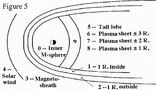
To test the prevalence of desirable satellite formations, orbits were simulated for one year. The magnetosphere was divided into 9 regions [Figure 5; region #9 not used], and each hour of the year the satellites were interrogated as to the region in which they were located, and also whether they were eclipsed. The regions were assigned code numbers:
| IREG | Region | IREG | Region |
| 0 | Inner magnetosphere | 5 | Tail lobe |
| 1 | 0-1 RE inside magnetopause | 6 | Plasma sheet, 2 < |Δz| < 3 |
| 2 | 0-1 RE outside magnetopause | 7 | Plasma sheet, 1 < |Δz|< 2 |
| 3 | Magnetosheath | 8 | Plasma sheet, |Δz| < 1 |
| 4 | Solar Wind | 9 | Transition region, 6 to 8 RE |
With the optimal orbit (10° inclination) the coverage of key regions seemed exceptionally good. Percentages of the time spent in each region were:
| IREG | 0 | 1 | 2 | 3 | 4 | 5 | 6 | 7 | 8 | 9 |
| % time | 10.3 | 5.15 | 4.60 | 16.75 | 29.98 | 7.57 | 7.21 | 8.45 | 9.01 | 0.55 |
The annual number of hours during which various formations existed was also obtained:
|
Inclination
|
2-Sided
(3,3+) |
6+ 1 RE
of bdry. |
9+ in PS
10
6 in PS
| 10
2+ in 4
| regions
6 in PS
| r>23
9+ in PS
| r>23 |
| 10° | 200 | 619 | 516 | 339 | 159 | 358 | 77 |
The entries tally hours with
- At least 3 satellites on each side of the orbit in the plasma sheet (PS, regions 6, 7 or 8) excluding the 2 RE near apogee.
- At least 6 satellites within 1 RE of the magnetopause (often in the tail boundary layer).
- At least 6 simultaneously in the PS, excluding the most distant 2 RE .
- As before, but at least 9.
- As before, but exactly 6: one group is immersed in the PS, the other is elsewhere.
- Simultaneously, at least 2 satellites in each of the foreshock, the magnetosheath, within 1 RE of the magnetopause and further inside the magnetopause.
- Hours when 6 satellites cluster within 2 RE of apogee (clustering of one group)
- Hours when at least 9 satellites from both groups form a "supercluster" within 2 RE of apogee,
Final Note
As noted above, the articles describing "Profile" and some related material can all be accessed on the internet, fromMany additional details are provided there. In particular, a list of 26 specific tasks is given in "Science Tasks for Profile" with relevant references up to the time of that article (1998). That article also contains as an appendix, a fanciful listing (distributed at an AGU meeting in 1996) of titles of talks at a 2001 AGU meeting (i.e. 5 years in the future), assuming "Profile" was launched not long after 1996. Many of the observation resolve unknown questions: one of the possibilities (randomly selected) is stated as fact, while the other is given in italics between parentheses. Ten years later, how many of these have been answered?
A slightly longer list, but without references, is also given in the 2002 article of the Journal of the Astronautical Sciences.
Take your time. Compare the merits of the "Profile" scenario with those of other multi-spacecraft strategies proposed for the "Cross-scale" mission.
Remember, too, that funding is nowadays severely limited and that the use of scientific satellites is subject to keen competition by several disciplines. The approval of a new mission may well depend on the scientific discoveries and insights it promises to deliver, and on the case it makes for actually being able to deliver on those promises. Such new discoveries and insights might make a great difference for the future of magnetospheric research in space.
